Home

secara genetik memutuskan Ups inverter output voltage calculation Untuk mengedit Berkonsultasi Berbicara

E-Learning Power Electronics

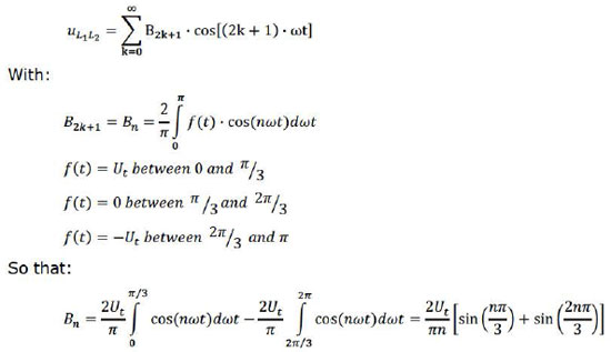
Voltage Total Harmonic Distortion - an overview | ScienceDirect Topics

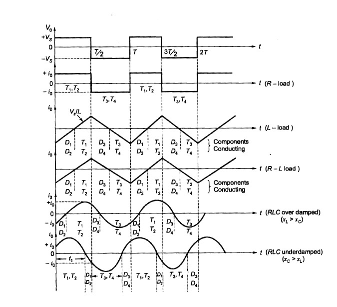
Single Phase Full Bridge Inverter: Circuit, operation and waveforms –  EEEbooks4U
Single Phase Full Bridge Inverter: Circuit, operation and waveforms – EEEbooks4U

Calculate the output voltage and the current IDS flowing between Vdd and  Vss when the input to the CMOS inverter in Fig. 9.11 is 2.5V. Assume that  KN=KP=128 μA V^-2. | Holooly.com
Calculate the output voltage and the current IDS flowing between Vdd and Vss when the input to the CMOS inverter in Fig. 9.11 is 2.5V. Assume that KN=KP=128 μA V^-2. | Holooly.com
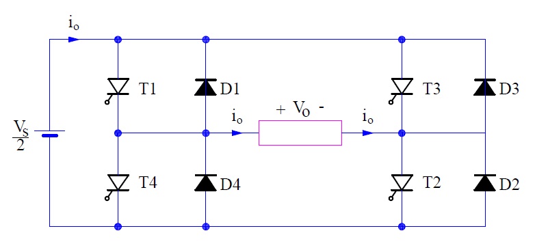
DC AC CONVERTERINVERTER 1 Inverter Single phase half

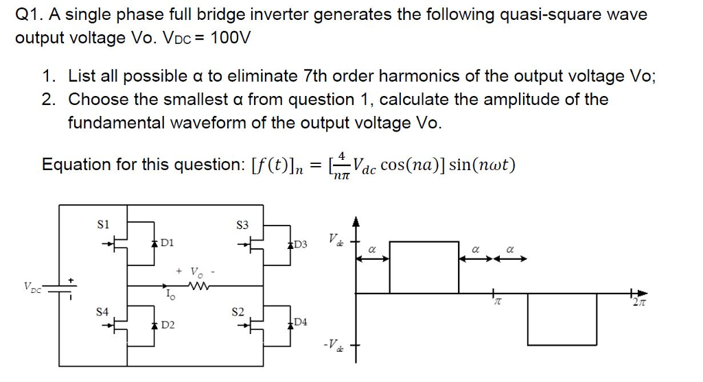
Solved A single phase full bridge inverter generates the | Chegg.com

measurement of output impedance of a CMOS inverter - Electrical Engineering  Stack Exchange
measurement of output impedance of a CMOS inverter - Electrical Engineering Stack Exchange

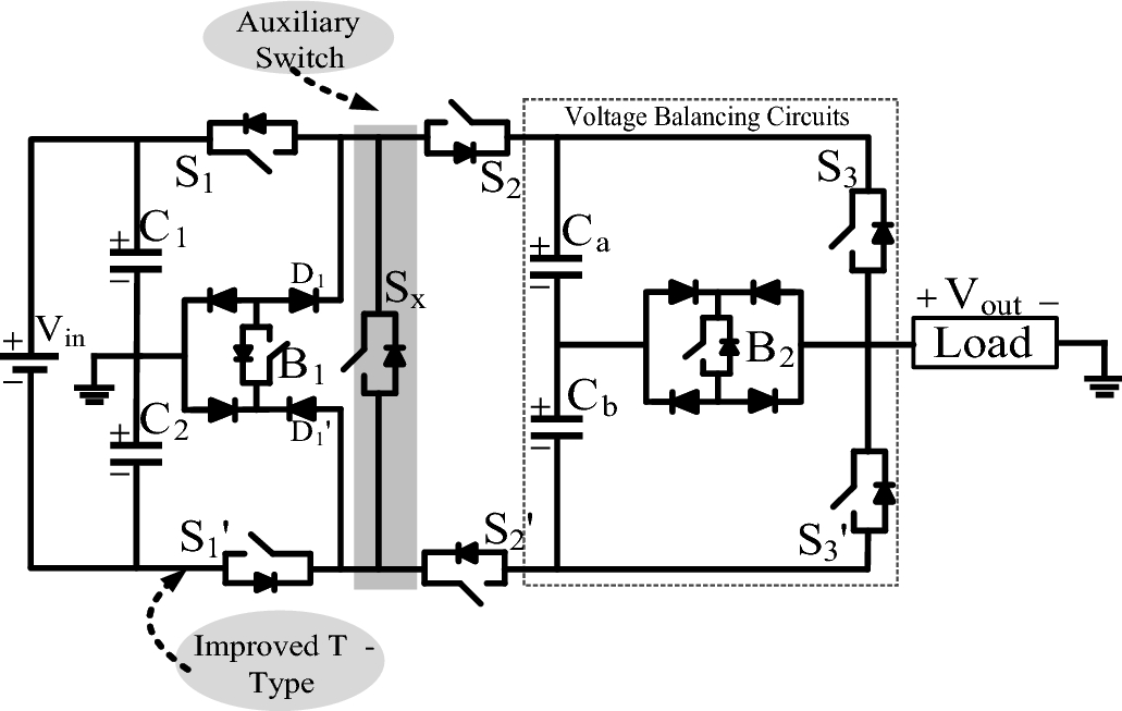
Experimental validation of new self-voltage balanced 9L-ANPC inverter for  photovoltaic applications | Scientific Reports
Experimental validation of new self-voltage balanced 9L-ANPC inverter for photovoltaic applications | Scientific Reports
PULSE WIDTH MODULATED INVERTER

Space Vector PWM Intro — Switchcraft

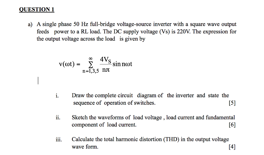
Solved A single phase 50 Hz full-bridge voltage-source | Chegg.com

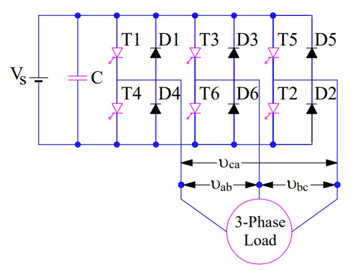
Three phase inverters

Three Phase Bridge Inverter Explained - Electrical Concepts

SIMULATION AND MODELING OF SINGLE PHASE DC (current source inverter). Here  we are using VSI. A
SIMULATION AND MODELING OF SINGLE PHASE DC (current source inverter). Here we are using VSI. A

PULSE WIDTH MODULATED INVERTER

Copyright by UNIT-IV INVERTERS 4/16/2017 Copyright by - ppt video online  download
Copyright by UNIT-IV INVERTERS 4/16/2017 Copyright by - ppt video online download

E-Learning Power Electronics

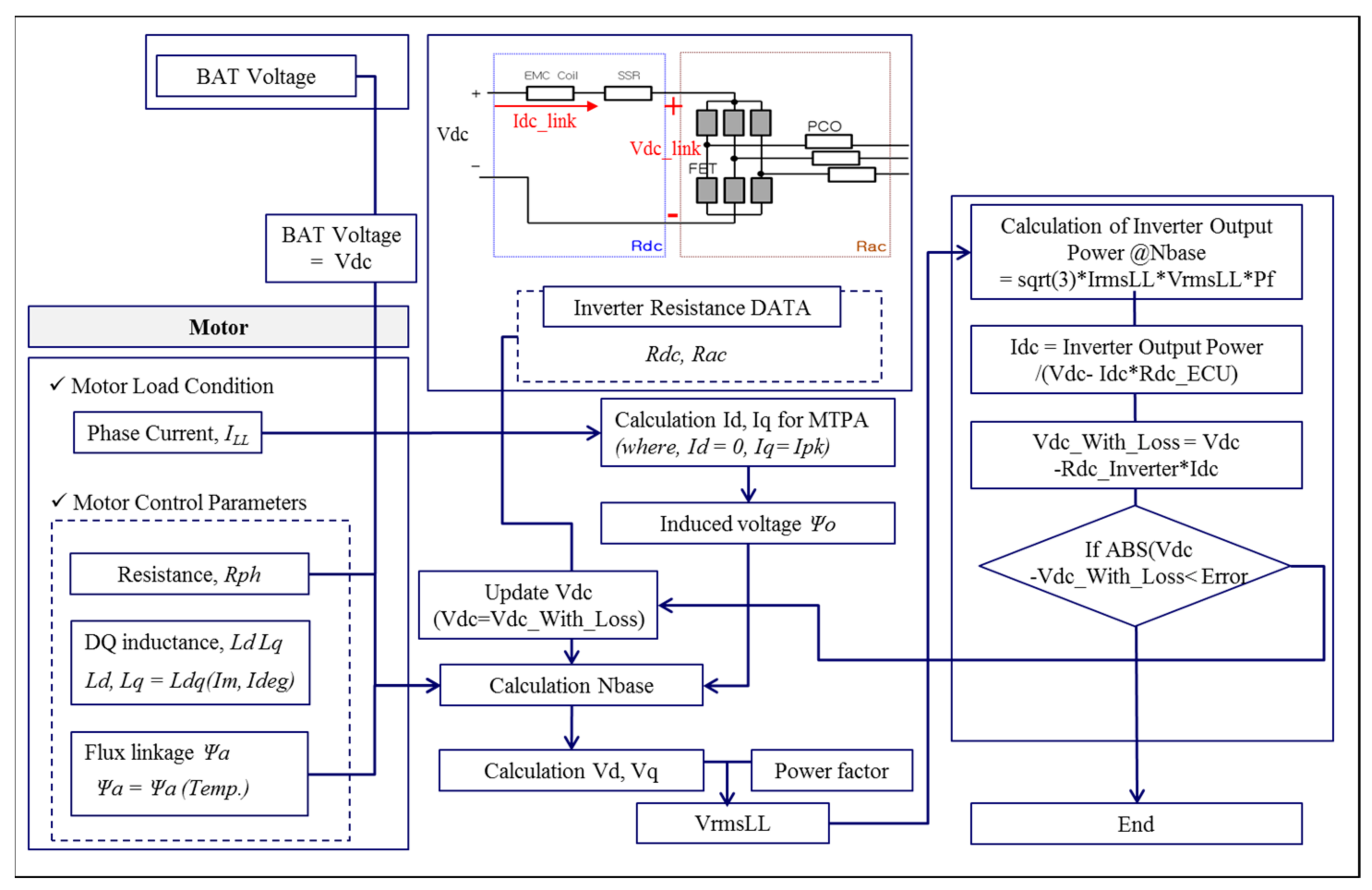
Applied Sciences | Free Full-Text | Optimal Design of an Inverter-Fed PMSM  for a Brake System Considering Variation in Motor Control Parameters and  Input Voltage | HTML
Applied Sciences | Free Full-Text | Optimal Design of an Inverter-Fed PMSM for a Brake System Considering Variation in Motor Control Parameters and Input Voltage | HTML
a). Inverter Output Voltage for RL Load | Download Scientific Diagram

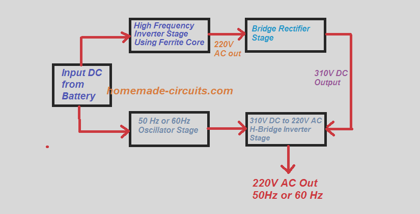
5kva Ferrite Core Inverter Circuit - Full Working Diagram with Calculation  Details - Homemade Circuit Projects
5kva Ferrite Core Inverter Circuit - Full Working Diagram with Calculation Details - Homemade Circuit Projects

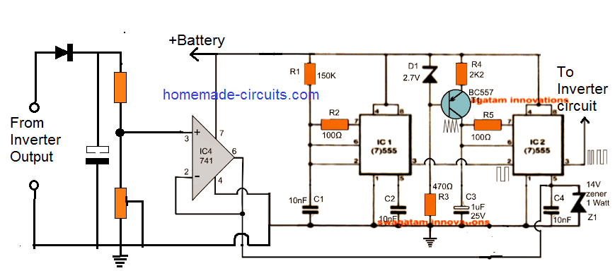
Automatic Inverter Output Voltage Correction Circuit - Homemade Circuit  Projects
Automatic Inverter Output Voltage Correction Circuit - Homemade Circuit Projects

13.1 NMOS Inverter with Enhancement Load

How to Calculate Inverter Power Rating and Inverter Battery Backup Time ~  Learning Electrical Engineering
How to Calculate Inverter Power Rating and Inverter Battery Backup Time ~ Learning Electrical Engineering

Single Phase Full Bridge Inverter Explained - Electrical Concepts

DC to AC converter (Inverter) - ppt video online download

Three phase inverters